| T O P I C R E V I E W |
| B112 |
Posted - 03/05/2007 : 18:16:50
The following article is about putting 280S K-Planes on a Formula 271 by Brett Becker:

1. The 280S K-Plane kit comes with tabs, mounting hardware, wiring harnesses and pumps. Hydraulic hoses and mechanical indicator cables are sold separately because of the length differences between boats these tabs can be used on. Measure the distance from the tabs to the indicator on the dash with a tape measure and the distance from the pumps to the tabs and order the proper length of hoses and cables.
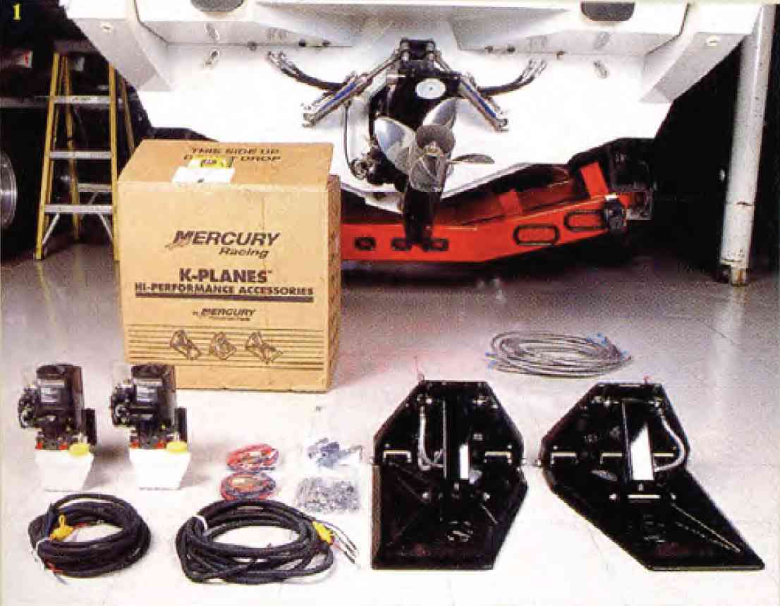
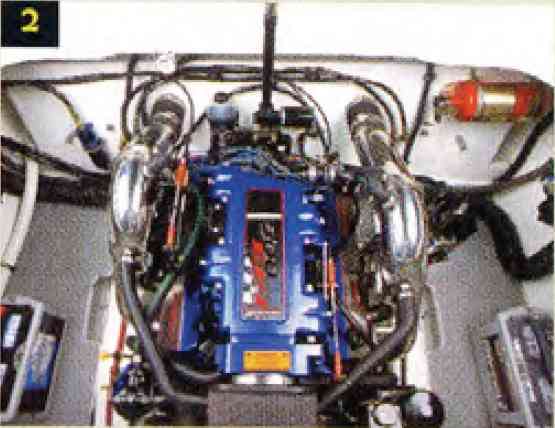
2. The bilge had enough room to work, but would need some disassembly before we could begin.
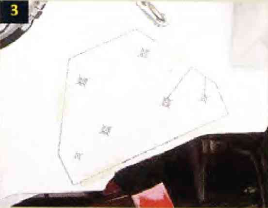
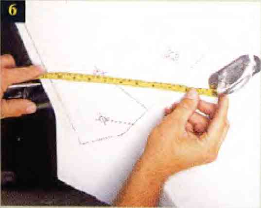
3. The kit comes with paper patterns that show you wheree to drill holes in the transom. We placed the bottom of the pattern in the customary location, three-quarters of an inch above the running surface between the outer stake and then chine. Make your measurement and draw a straight line to align with the bottom of the pattern. Then measure the distance from the strake and chine to ensure the patterns are in the same spot on each side.
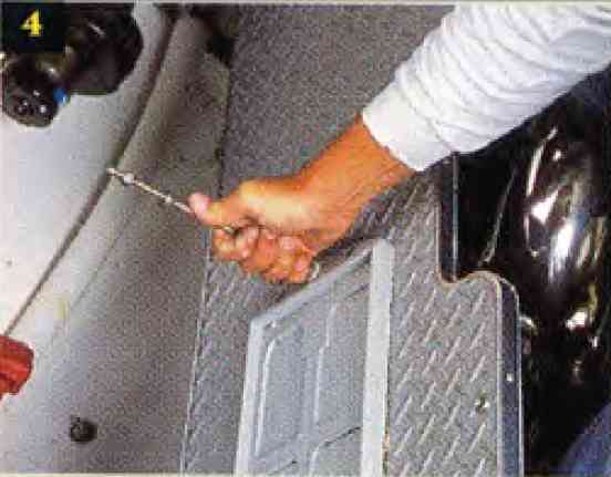
4. Before we go any further, we had to remove the batteries and the flooring that flank the engine.
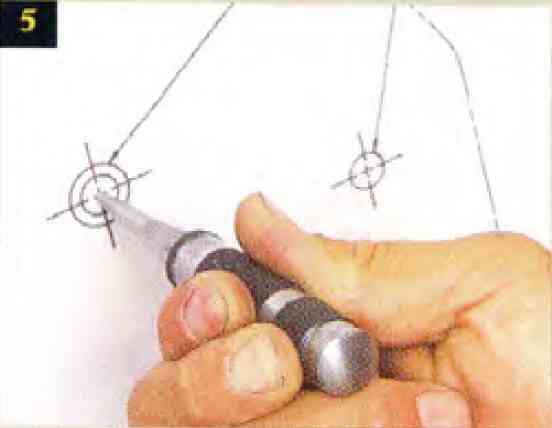
5. Take a punch and put it dead-center in each mark on the pattern.
6. Before drilling pilot holes, it's a good idea to make some measurements to find out where the drill bits will be punching through in the bilge area.
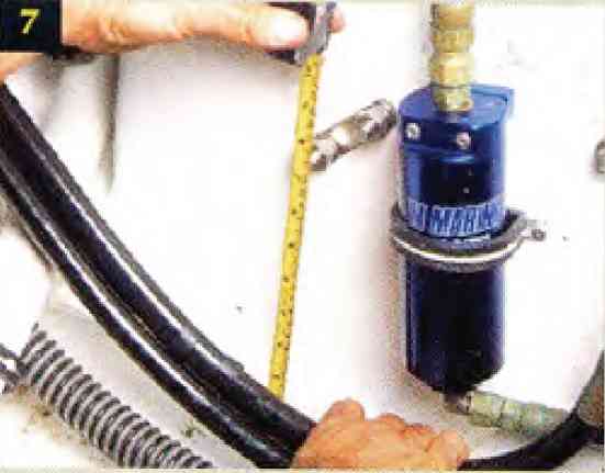
7. In our case, we had to hold the hydraulic steering hoses out of the way while drilling the transom.
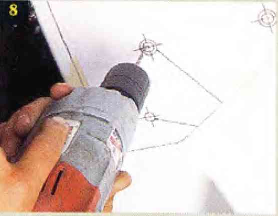
8. Drill pilot holes with a smaller bit than called for in the directions.
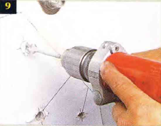
9. Once you have the pilot holes drilled, use the bit sizes recommended in the instructions and drill your mounting holes. This is where air tools can come in handy.
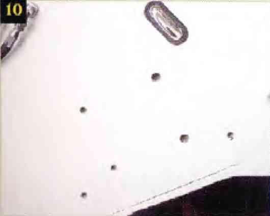
10. Remove the paper patterns and this is what you see. Note the line we drew earlier to align the pattern.
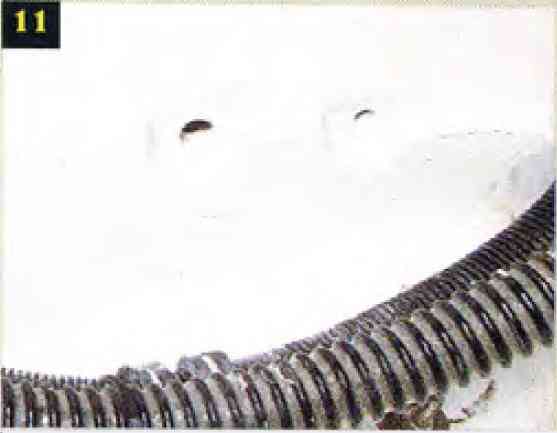
11. Because Formula builds its boats with a "grid" system, we had to grand away portions of the grid so that the fender washers would sit flat. Again, air tools make this much easier. After grinding, we vacuumed out the debris and brushed on some plain white gelcoat.
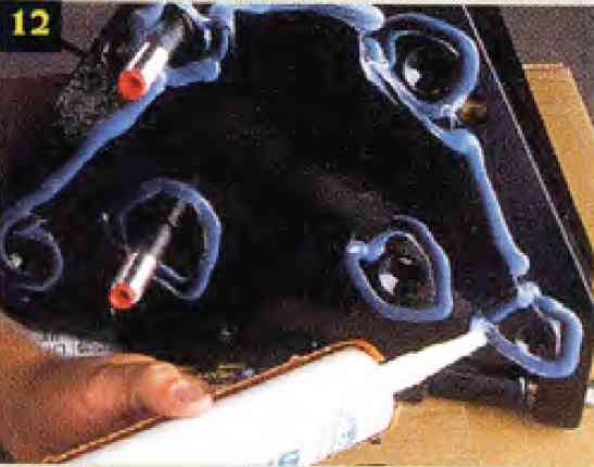
12. Applay clear silicone to the mounting flange, around each bolt hole.
13, 14. Mount the tab to the transom and apply pressure to spread the silicone.
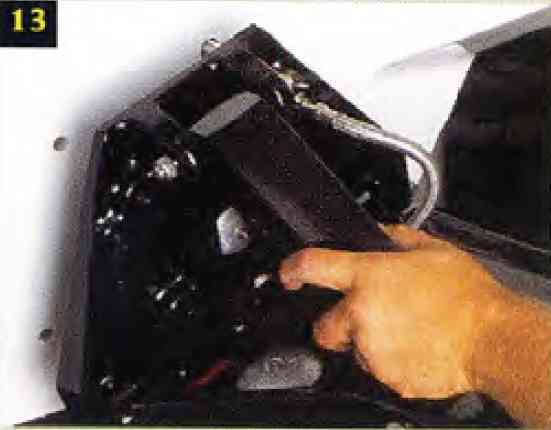
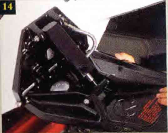
15. Push the supplied mounting bolts through the holes in the tabs and transom and have your assistant torque the nuts on the inside. Torque the bolts in a crisscross pattern, as with a car wheel, to distribute the load evenly.
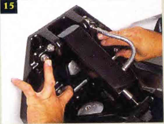
16. Though you only applied silicone around the bolt holes, the mounting torque will squeeze it out around the sides. Use a bondo spreader, which removes the excessa and forces the silicone into the gap between the tab flange and the transom.
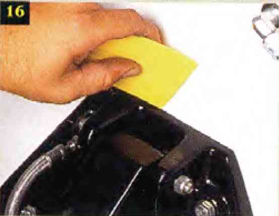
17. Remove the plug from the undrilled hole the indicator cable will run through.
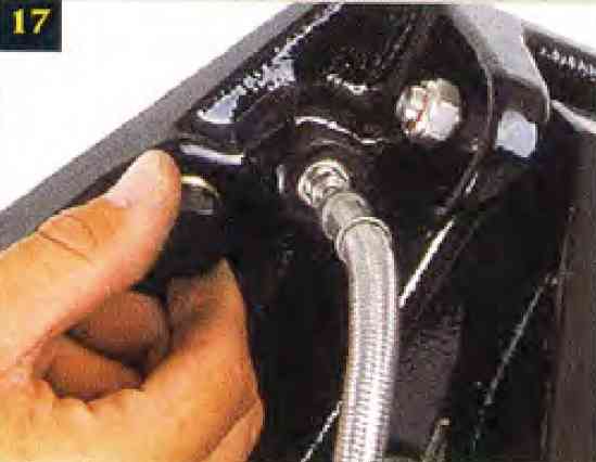
18. Because the paper pattern doesn't show the hole needed for the indicator cable, it's necessary to drill the hole for it after the tab is in place.
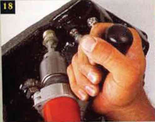
19. Screw in the plastic fitting for the indicator cable.
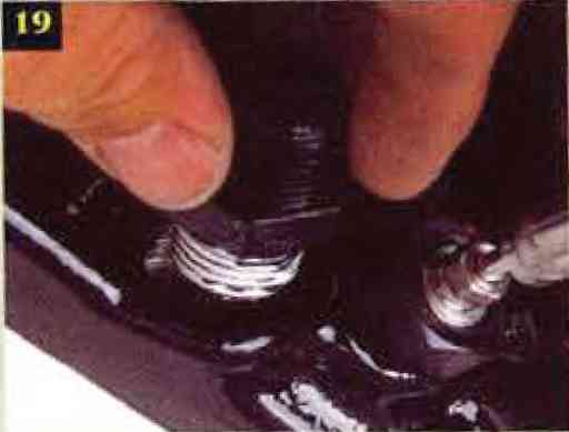
20. Run the indicator cable through the hole, screw on the sealing cap. Dab on some sealant or apply Teflon tape to the threads. Then use the supplied hardware to fasten the cable to the tab.
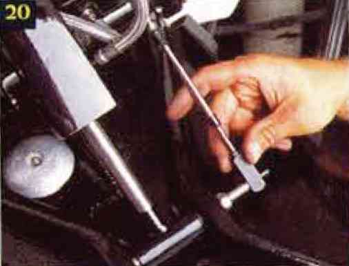
21. Brush on some clear resin around the mounting hardware in the bilge for extra sealing. Note how the bolts and washers sit nicely in the cutouts we ground out the grid system.

22. Attach and route the hydraulic lines and indicator cables.
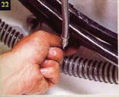
23. Route the indicator cables under the gunwale toward the panel on the dash and run the wiring harnesses to the switches just forward of the throttles.
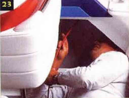
24. Our project boat came with good quality switches, so we left them alone. Connect the Mercury wiring harnesses to the switches.
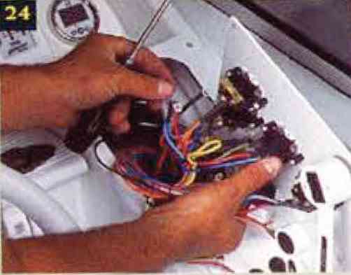
25. We routed the harnesses for the trim pumps with good quality switches, so we left them alone.
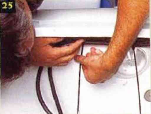
26. Per U.S. Coast Guard regulations, we used one cushion clamp every 12 inches. Taking it a step further, we used two nylon tie-wraps between each cushion clamp.
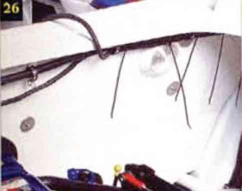
27. The best place for the trim pumps, in this case, was just above the stringer rib, mounted as low on the firewall as possible.
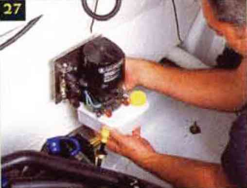
28. Remove the mounting bracket from the pump and fasten it to the firewall, through-bolting it with stainless hardware.
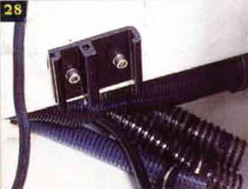
29. Slide the pump back onto the bracket.
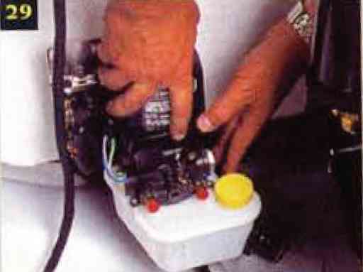
30. Torque the bolt to secure the pump in place.
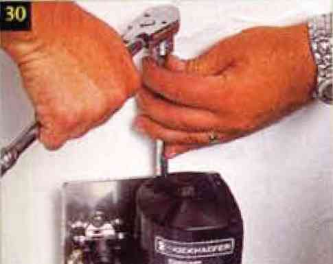
31. Cut the supplied wiring harness to the proper length.
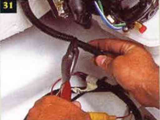
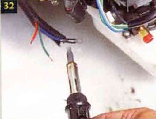
32. Crimp on eyelet connectors and wrap with heat shrink tubing. Soldering the connectors makes the installation even better.
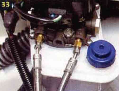
33. Attach the hydraulic hoses and fill the resevoirs with 10W-30 motor oil. Note that we replaced the stock resevoir caps with the leak-free models from Turbosonic.
34. With both trim pumps mounted, we secured the harness with cushion clamps. Again one clamp every 12 inches.
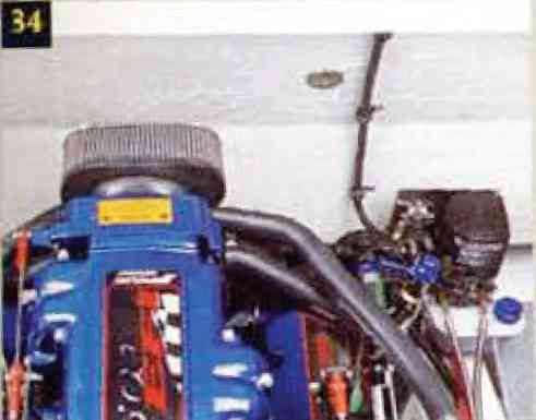
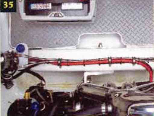
35. To power the pumps, we routed the harness from each to the small positive terminal on the starter. This is the starboard side after the flooring and battery were reinstalled.
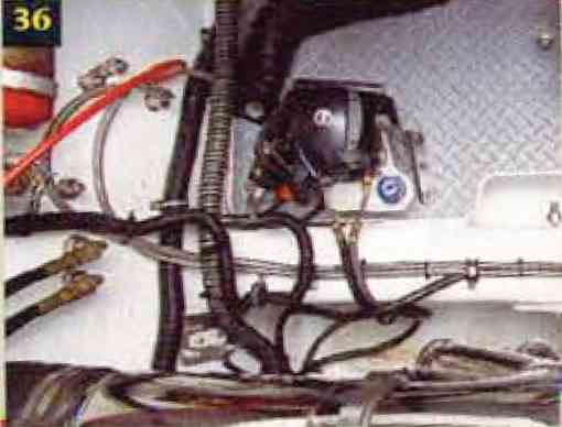
36. This is the port side after the flooring and drive-trim were reinstalled.
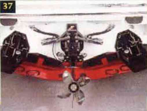
37. Installation is complete.
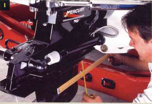
1. Pick your starting point, tabs or drive. We started with the drive. Place a straightedge along the keel so it extends out to the drive. Be sure it is parrellel with the keel, otherwise your measurements will be inaccurate. Have your buddy at the wheel to adjust the trim switch as you measure from the straightedge to the bottom of the cavitation plate. Measure at the front and rear and adjust the drive so that both measurements are equal. It would be best to use a metal straightedge, but, well, we couldn't find one so we opted for a new yardstick, which checked out OK.
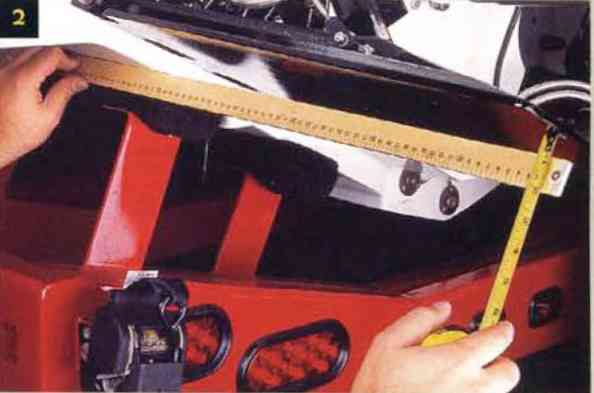
2. In aligning the tabs, the procedure is large the same. Place the straightedge on the running surface just forward of the trim tab. Again, be sure the staightedge is parrallel fore and aft so your measurements are accurate, and again measure at the front of the tab and at the rear. Have your buddy "tap" the tab switches to make minute adjustments until the measurements are equal.
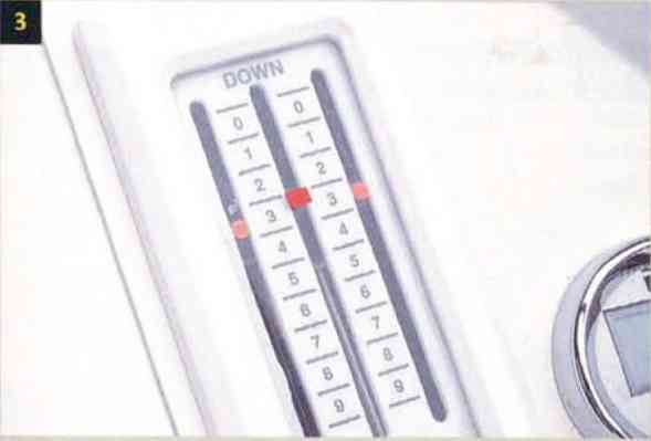
3. On the Mercury Racing panel , we had to place the tape "over" the neutral spot for the drive. When the drive is set at neutral, the indicator peg disappears behind the tape, which suited us just fine. Note that the tabs are at neutral on the panel, just a bit higher on the scale (by the numbers) than the drive.
4. For the tabs, we cut an extra long piece of tape so we could place it over the frame of the indicator panel. This creates a bold image to the eye and makes it easier to quickly align the indicator peg with the tape.
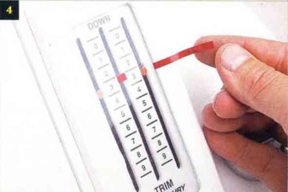
5. This is what the panel looks like after we installed the tape on the both sides. See how easy it would be to align the pegs with tape? And since we used red reflective tape, direct sunlight shouldn't make it any more difficult to see.
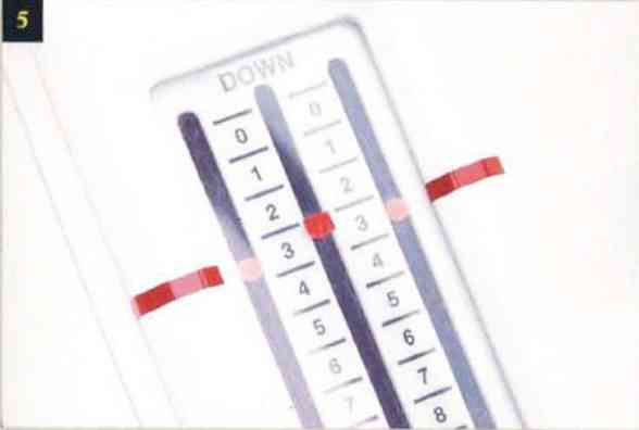
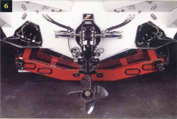
6. After it's all done, the tabs are parrellel, as is the drive, which should give you a good starting point for negotiating head-on seas. Be sure to trim up the drive and tabs before trailering it next time.
|
|
|

